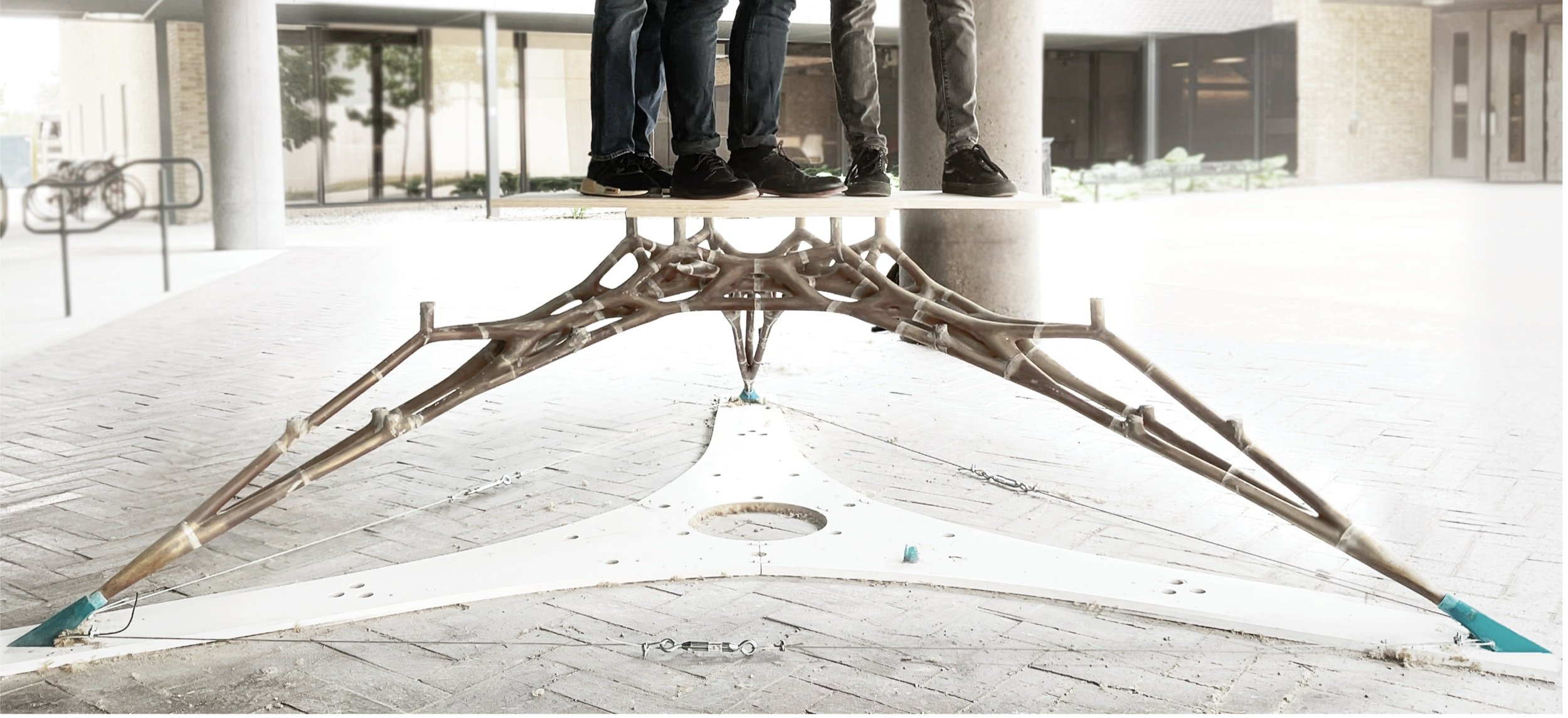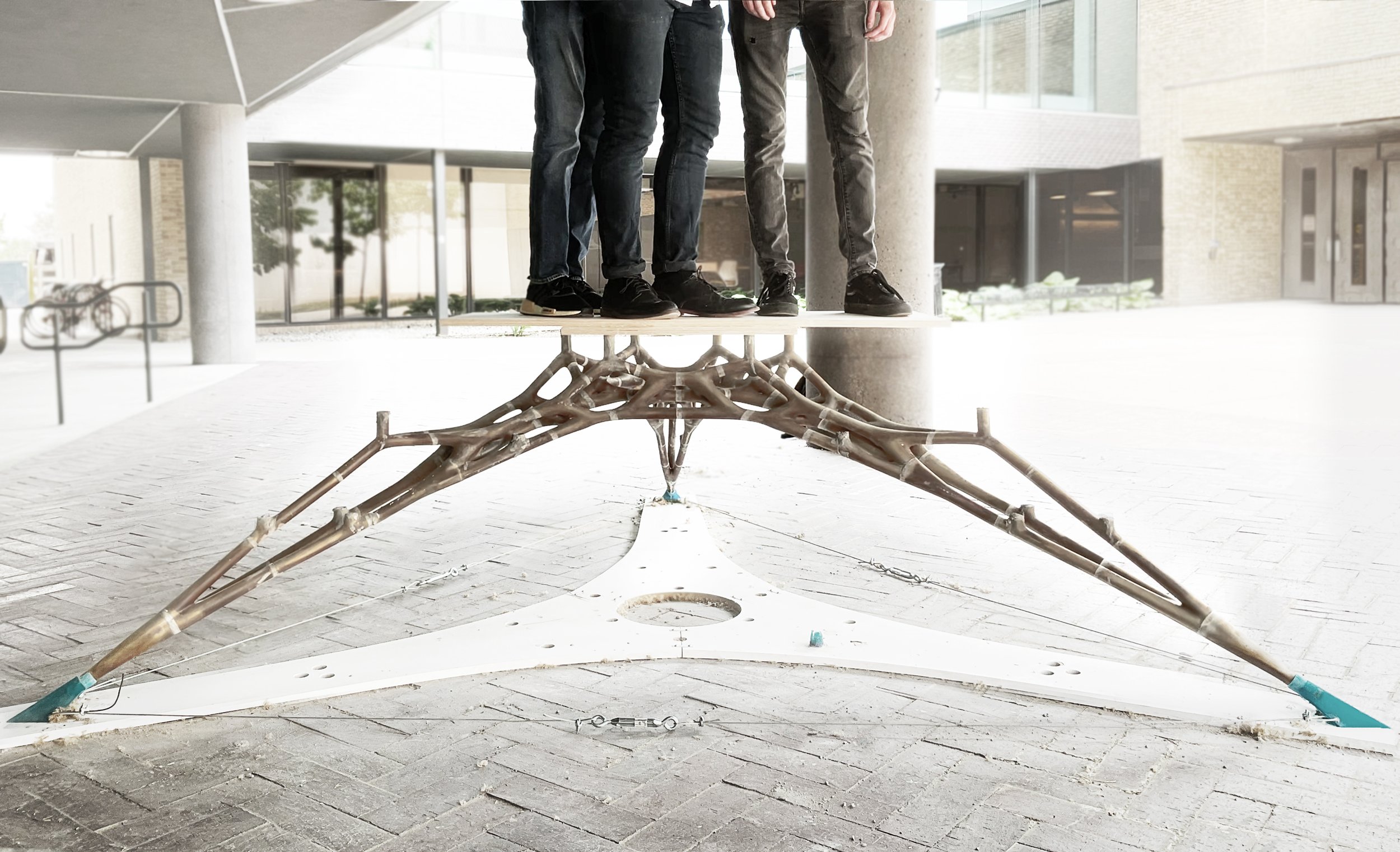
Cavity Shell
Sequential Cast-in-Place Method to CreateCompression-Only Structures with Ultra-Thin Additively Manufactured Form-work Assemblies.
Cavity Shell
Sequential Cast-in-Place Method to CreateCompression-Only Structures with Ultra-Thin Additively Manufactured Form-work Assemblies.
Team : Stuti Bindlish Instructor: Dr. Mania Aghaei Meibodi Year: 2023
Location: Ann Arbor MI, USA Phase: Built Prototype
introduction
The compression-only structure's impressive strength-to-weight ratio allows it to span large spaces using significantly less material. However, prefabricated masonry or concrete components used to construct compression-only structures are prone to damage during handling and transportation and contribute to CO2 emissions. Additionally, assembling these components requires heavy falsework, which results in material wastage and increased construction costs. This research paper presents an alternative approach to constructing compression-only structures by introducing a new in-situ construction approach based on coupling 3D-printed ultra-lightweight plastic formwork on- site and sequential casting of the formwork in compression.
This is achieved through developing: 1. a new construction method base on the assembly of lightweight 3D printed plastic formwork in compression only from that is then sequentially cast with concrete in place; 2. an integrative formwork system informed by structural and casting logics (i.e., flowability, the height of the casting point in relation to hydrostatic pressure, placement of formwork interface in alignment to internal forces in the structure; 3.a parametric model for translating force-form diagram to integrative formwork. To verify this research method, Cavity Shell, a 1:1 scale compression-only table leg structure measuring 1.4 meters in radius and 0.8 meters in height, was designed and built. This ultra-lightweight formwork took less than 48 hours to assemble and sequentially cast by two people. This research demonstrates the potential to rethink the construction of compression-only structures by minimizing the material used and improving economic and environmental efficiency in their construction life cycle.
Design Process
The design process consists of two major steps a) the design of the compression-only structure through the computational form-finding method and b) the formwork system design informed by structural and casting logic. Form-Finding of Compression- Only Structure: This research utilizes 3D Graphic Statics (3DGS) as a form-finding method to generate a compression-only structure as the first step of the design process. This method is a three-dimensional extension of Graphic Statics (GS) principles in 3D Space. GS is a graphical methodology of solving the forces acting in equilibrium on a rigid structure by representing forces as vectors or polygons. 3DGS is utilized to derive 3D funicular structural lines by subdividing force polyhedrons (Akbarzadeh et al. 2015) based on reciprocal polyhedral diagrams (comprising edges and vertices). With geometrically linked force and form diagrams, this approach permits alterations in support positions, magnitude and angle of applied forces, and their overall distribution.
Formwork Discretization
The size of the formwork segments directly correlates with the build volume of the 3D printer. To meet these fabrication constraints, the overall design of the formwork is discretized into segments. The cutting plane of these segments is perpendicular to the direction of the dominant compressive forces to preserve the structural integrity of the formwork and ensure these formwork segments are in compression once assembled . An algorithm is developed to automatically discretize the formwork based on the bed volume of 3D printer input. SLA 3D Printing of a highly complex, detailed, and ultra-thin formwork is done using ABS-like resin. This fabrication method enables the 3D printing of sophisticated interlocking joints for the formwork segments at a minimum layer height of 25 microns, reducing the risk of any leakage during the casting process and optimizing material consumption in formwork production. The formwork features (a) hydrostatic membrane, (b) casting inlet, and the joinery connection are integrated, and 3D printed as a part of the formwork segments, making it a uniform geometry for casting
Casting Inlets
Casting Inlets are introduced to enable SC into the cavity of the assembled compression- only formwork. The placement and height of these inlets within the formwork depend on the achievable casting height with respect to hydrostatic pressure for each casting cycle. The formwork has numerous casting inlets for each pouring cycle. The inlet openings are strategically located on the same Z plane, which enables the concrete to flow through the interconnected channels, filling each segment adequately until complete saturation is achieved during the designated casting cycle
Assembly and Scaffolding:
The discrete segments of the formwork are assembled without any mechanical connections. Instead, the compression- dominant structural shape of the formwork enables a simple interface design, utilizing a male-female interlocking mechanism. These interlocking features ensure precise alignment of the formwork segments during assembly and prevent any concrete leakage during the casting process. A minimal scaffolding system was designed. This system provides support during the formwork assembly and prevents any deflection in the formwork during the casting process. It consisted of 3D-printed upper and lower holders, threaded rods, and turnbuckles, allowing the scaffolding system to facilitate the structure's leveling in cases of variations in the ground level.
Formwork Design:
A parametric model was developed to integrate formwork features based on the structural and casting logic. In Cavity Shell, the SC was divided into three casting cycles based on the height value achieved from the hydrostatic equation. This division determined the placement of the 1mm thick hydrostatic membranes, resulting in 15 cold joints in the formwork. The position and alignment of these membranes informed the integration of casting inlet parameters, such as their position, height, and diameter, into the parametric model. Additionally, this computational model also analyzed the integration of casting inlets parallel to horizontal branches in the form to utilize pressure differences and assist in directing the concrete flow horizontally. Based on the formwork prototyping, a constant thickness of 1.5 mm was maintained throughout the formwork, making it ultra-lightweight to transport to the site.
3D Printing:
A setup of three SLA 3D printers, each having a build volume of 219x123x250 mm, was used to 3D print the formwork of Cavity Shell using ABS-like resin. The entire formwork was segmented into 54 discrete 3D printed segments based on the build volume of the 3D SLA printers and was distributed over 27 prints (Figure 9). These 54 discrete segments were printed at a layer height of 50 microns culminating in a total printing time of approximately 400 hours. In addition to these formwork segments, 21 custom scaffolding structures, accounting for a total of 42 parts, i.e., 21 lower and 21 upper parts with a 25% infill, were also printed on the SLA 3D printer using ABS-like resin and took around 60 hours of print time to complete.


